Introduction on PE100A (UTY-DSGXZ*)
ASUS PE100A (FGL model name UTY-DSGXZ*) can be used as AIRSTAGE Cloud Edge Supervisor.

Things to prepare before using this product
This product requires the use of one of the following optional transmission adaptors. Procure in advance.
| Name & Shapes | Q'ty | Remark |
|---|---|---|
|
Transmission Adaptor (U10 USB Network Interface -TP/FT-10 Channel)
|
1 |
Model: 75010R (Echelon Corporation) |
|
Transmission Adaptor (U60-FT DIN Network Interface)
|
Model: 75060R-40 (Echelon Corporation) |
This product requires the use of the following power code and power adapter. Procure them in advance.
| Name & Shapes | Q'ty | Remark |
|---|---|---|
|
Power code
|
1 | Connector type: C13 (IEC-60320) |
|
Power adapter
|
1 | ・Input voltage 100 to 264VAC ・Output voltage 12VDC with 2A DC load ・0 to 40°C operating temperature ・Outer Diameter 5 mm / Inner Diameter 2.5 mm, center + |
How to connect to the power supply
Connect to the power supply as shown in the figure below.

Wireless LAN Antenna
To open the "Activation" screen for connecting this product to the cloud, your PC or smart device must be connected to this product via Wireless LAN.
For details on the connection method, refer to "Initial Setup".
To perform the above, connect the antenna to ANT.4 and ANT.5.

Internet connection
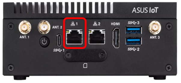
Connect LAN port 1 to the Internet with Ethernet Cable. The connection can be checked on the "Cloud Connection" screen.
If the connection is not possible, make sure IPSEC pass-through setting of a router is enabled. Refer to the router's manual for details on how to check IPSEC pass-through.
VRF connection
Connect Echelon® U10 or U60 to USB port 3.
Fujitsu General VRF system is connected to the PE100A via the above device.
Connect U10/U60 while the PE100A power is off.
When connecting U10/60 to PE100A after turning on the power, such as when you forgot to connect U10/U60 or when it is disconnected, be sure to turn off the power once before connecting.

Wiring rule
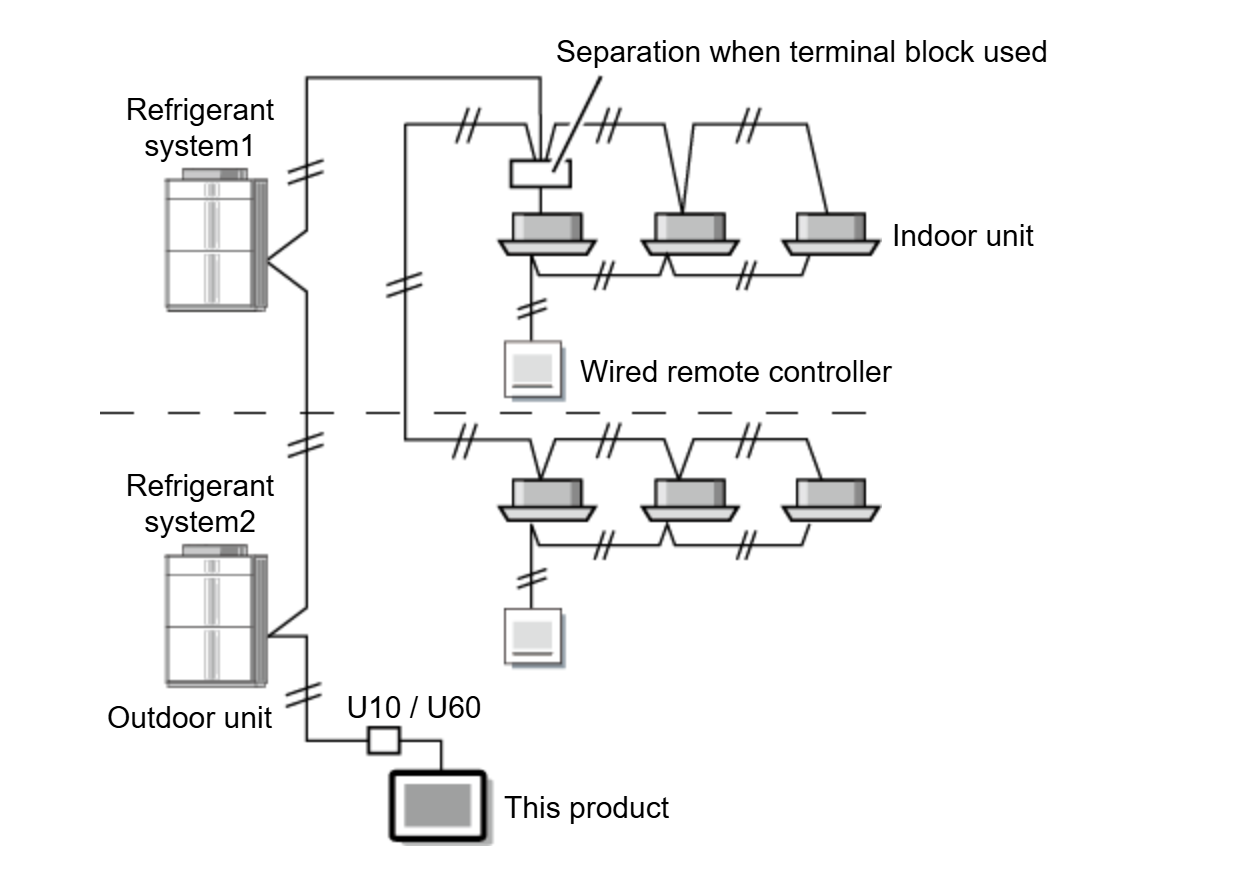
When wiring between the outdoor unit, indoor unit, and this product, refer to the indoor unit and outdoor unit installation manuals.

Wire the transmission cable to any one of the following:
(1) Transmission terminal block inside the indoor unit (Fig. 1)
(2) Terminal block for branch transmission cable (Procured at the site) (Fig. 2)
(3) Transmission terminal block inside the outdoor unit (Fig. 3)
Fig. 1

Fig. 2

Fig. 3

Connection of Ventilator, Roof top unit, FGL Split System and LoRaWAN devices, etc.
Connect to LAN port 2 with Ethernet Cable.
For the devices to be connected via Wireless LAN, use a Wireless LAN Access Point.

External Input
This function uses the DI1 and DI2 ports on the PE100A.
Refer to "Change the setting of Edge Supervisor" to set it.

External Output
This function uses the DO1 and DO2 ports on the PE100A.
The functions in the table below can be used. For the electrical characteristics and connection methods, refer to the PE100A installation manual.
| Port | Condition |
|---|---|
DO1 |
24V: 1 or more registered indoor units are operating. |
| 0V: All registered indoor units are stopped | |
DO2 |
24V: An error occurs somewhere in this product or registered indoor units and outdoor units. |
| 0V: This product and all registered indoor units and outdoor units are operating normally. |


